In a digital system there are only a few basic operations performed, irrespective of the complexities of the system. The basic operations are
1) AND
2) OR
3) NOT
The AND, OR and NOT operations are discussed here
1) The AND Operation
A circuit which performs an AND operation is shown in following figure. It has 2 inputs and one output.
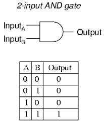
Digital signals are applied at the input terminals marked A and B, the output is obtained at output terminal marked 'Output' and it is also a digital signal. The AND operation is defined as : the output of AND gate is 1 if and only if all the inputs are 1. Mathematically, it is written as
Y = A AND B AND C......AND N
= A * B * C * ..... * N (1)
where A,B,C,.....N are the input variables and Y is the output variable. The variables are binary, i.e. each variable can assume only one of the two possible values, 0 or 1. The binary variables are also known as logical variables.
Equation (1) is known as the Boolean equation or the logical equation of AND gate. The term gate is used because of the similarity between the operation of a digital circuit and a gate. For example, for an AND operation the gate opens (Y=1) only when all the inputs are present, i.e. at logic 1 level.
2) The OR Operation
Following figure shows an OR gate with 2 inputs and one output.
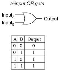
The OR operation is defined as : the output of an OR gate is 1 if and only if one or more inputs are 1. Its logical equation is given by
Y = A or B or C......OR N
= A + B + C + ...+ N
3) The NOT Operation
Following figure shows a NOT gate, which is also known as inverter. It has one input and one output.
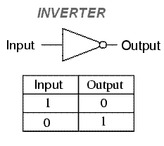 Its logical equation is given by
Y = NOT A
= A'
1) AND
2) OR
3) NOT
The AND, OR and NOT operations are discussed here
1) The AND Operation
A circuit which performs an AND operation is shown in following figure. It has 2 inputs and one output.
Digital signals are applied at the input terminals marked A and B, the output is obtained at output terminal marked 'Output' and it is also a digital signal. The AND operation is defined as : the output of AND gate is 1 if and only if all the inputs are 1. Mathematically, it is written as
Y = A AND B AND C......AND N
= A * B * C * ..... * N (1)
where A,B,C,.....N are the input variables and Y is the output variable. The variables are binary, i.e. each variable can assume only one of the two possible values, 0 or 1. The binary variables are also known as logical variables.
Equation (1) is known as the Boolean equation or the logical equation of AND gate. The term gate is used because of the similarity between the operation of a digital circuit and a gate. For example, for an AND operation the gate opens (Y=1) only when all the inputs are present, i.e. at logic 1 level.
2) The OR Operation
Following figure shows an OR gate with 2 inputs and one output.
The OR operation is defined as : the output of an OR gate is 1 if and only if one or more inputs are 1. Its logical equation is given by
Y = A or B or C......OR N
= A + B + C + ...+ N
3) The NOT Operation
Following figure shows a NOT gate, which is also known as inverter. It has one input and one output.
Y = NOT A
= A'
No comments:
Post a Comment